|
|
|
AmpArray[32]
|
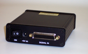
Applications: • Deformable mirror drive • MEMS/NEMS device drive & test The AmpArray[32]™ is a simple 32-channel amplifier unit capable of driving adaptive mirrors with actuator load capacitances in the 10pF – 10nF range, at the frequencies typically required to correct atmospheric turbulence. It contains no internal digital-to- analogue converters, and is intended to be |
||||
| driven by an external source of analogue control signals. | |||||
|
This analogue in–analogue out configuration was created to allow a deformable mirror to be controlled directly from high-level data acquisition and instrument control software, without requiring additional device driver software. The AmpArray[32] would typically be driven by a PC multi-channel DAC card supported by the user's preferred high-level software. The input specification matches the output characteristics of many popular DAC cards offered with the leading instrument control software packages. |
|||||
|
This simple yet versatile device comes in a compact enclosure and requires only a single +5V dc power supply input. It offers a convenient and economical way to control a variety of modern MEMS-based and bimorph deformable mirrors. A variety of output options can be offered as semi-custom drive solutions. |
|||||
| System Characteristics | ||
| Number of amplifier channels | 32 | |
| Amplifier Gain | +19 ± 5% | |
| Input Characteristics | ||
| Input Voltage Range | 0V to +10V | |
| Input Impedance | 10kΩ | |
| Output Characteristics | ||
| Output Voltage Range | 0V to +190V | |
| Output Drive Current Limit | 45μA ± 40% | |
| Small Signal Bandwidth | 4kHz @ -3dB corner | |
| Slew Time with Capacitive Load (2.2nF load, 100V step) |
3.9ms typ. (10% to 90% of step) | |
| Physical Characteristics | ||
| Enclosure Dimensions | 126mm(D) × 106mm(W) × 34mm(H) | |
| Power In | +5V dc regulated, @ 0.2A | |
The AmpArray[32] has a unipolar output range, but it can also be used to drive mirrors requiring a bipolar drive signal. Application Note 1 explains how.
 The 32-channel AmpArray[32] is matched to the channel
count of popular DAC cards, and can be used to
drive a wide range of deformable mirror sizes.
The 32-channel AmpArray[32] is matched to the channel
count of popular DAC cards, and can be used to
drive a wide range of deformable mirror sizes.
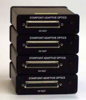
Several of the compact
AmpArray[32] units can be combined to form higher channel-count
drive systems. The image to the left shows a 128-channel
configuration formed from four AmpArray[32] units.
The maximum channel count
is typically limited by the DAC I/O capacity of the host computer.
Each amplifier channel's current limit is set to a nominal 50µA. There is a ± 40% spread in this value. The current limit is a safety feature of the amplifier, it is not the normal operating mode. The amplifier should be operated in the linear regime, not the current-limited regime.
The plot below shows the large signal step response for a low capacitance load (15pF) and for a high capacitance load (2.2nF). These values are typical of MEMS mirrors and bimorph mirrors, respectively. A 100V pk–pk square wave is applied, the voltage swing is between +20V and +120V.
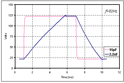 For the 15pF load, the rise and fall times are about 80µs, determined
by the 4kHz low pass filter. For the 2.2nF load, the large signal
step response is quasi-linear, with a 3.4ms rise time and a 2.5ms
fall time, determined by the current limit. There is a 2V overshoot
on exit from the current limited mode.
For the 15pF load, the rise and fall times are about 80µs, determined
by the 4kHz low pass filter. For the 2.2nF load, the large signal
step response is quasi-linear, with a 3.4ms rise time and a 2.5ms
fall time, determined by the current limit. There is a 2V overshoot
on exit from the current limited mode.
| System Connectors: | ||
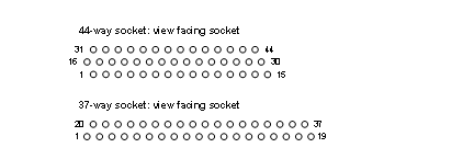
| Signal Input Connector: | 44-way HD22 (density-and-a-half) 'D'-type socket. | |
| HV Output Connector: | 37-way HD20 'D'-type socket. | |
| Power Supply Connector: | 0.1" pin miniature power jack. (Power supply is included). |
Pin assignment on the input (44-way) and output (37-way) 'D'-type connectors:
| Input Connector: 44-way | Output Connector: 37-way | ||||
| Pin No. | Signal | Pin No. | Signal | ||
| 1 | IN31 | 1 | GND | ||
| 2 | GND | 2 | HV1 | ||
| 3 | IN26 | 3 | HV3 | ||
| 4 | IN24 | 4 | HV5 | ||
| 5 | IN22 | 5 | HV7 | ||
| 6 | GND | 6 | HV8 | ||
| 7 | IN17 | 7 | HV10 | ||
| 8 | IN15 | 8 | HV12 | ||
| 9 | IN13 | 9 | HV14 | ||
| 10 | GND | 10 | GND | ||
| 11 | IN8 | 11 | HV17 | ||
| 12 | IN6 | 12 | HV19 | ||
| 13 | IN4 | 13 | HV21 | ||
| 14 | GND | 14 | HV23 | ||
| 15 | GND | 15 | HV24 | ||
| 16 | GND | 16 | HV26 | ||
| 17 | IN29 | 17 | HV28 | ||
| 18 | IN27 | 18 | HV30 | ||
| 19 | IN25 | 19 | GND | ||
| 20 | GND | 20 | HV0 | ||
| 21 | IN20 | 21 | HV2 | ||
| 22 | IN18 | 22 | HV4 | ||
| 23 | IN16 | 23 | HV6 | ||
| 24 | GND | 24 | GND | ||
| 25 | IN11 | 25 | HV9 | ||
| 26 | IN9 | 26 | HV11 | ||
| 27 | IN7 | 27 | HV13 | ||
| 28 | GND | 28 | HV15 | ||
| 29 | IN2 | 29 | HV16 | ||
| 30 | IN0 | 30 | HV18 | ||
| 31 | IN30 | 31 | HV20 | ||
| 32 | IN28 | 32 | HV22 | ||
| 33 | GND | 33 | GND | ||
| 34 | IN23 | 34 | HV25 | ||
| 35 | IN21 | 35 | HV27 | ||
| 36 | IN19 | 36 | HV29 | ||
| 37 | GND | 37 | HV31 | ||
| 38 | IN14 | ||||
| 39 | IN12 | ||||
| 40 | IN10 | ||||
| 41 | GND | ||||
| 42 | IN5 | ||||
| 43 | IN3 | ||||
| 44 | IN1 | ||||
© 2002–2011 Starpoint Adaptive Optics Limited