Starpoint Adaptive Optics
Product Preview
Hydraplex™ Channel Demultiplexer Unit
>> See also: Hydraplex™ HV Stage
Overview
Starpoint's Hydraplex™high channel count deformable mirror drive architecture
is intended for large adaptive optics installations.
It consists of a standard Channel Demultiplexer Unit that is common to
all variants, and a High Voltage Stage that can be
designed to provide user-specified drive characteristics.
The HV Stage provides the high voltage power amplifiers
needed to drive the deformable mirror. A variety of amplifier
types is available, to meet the requirements of a diverse range
of deformable mirror characteristics.
The Channel Demultiplexer Unit (CDU) provides a Serial FPDP data
interface to the control computer, 16-bit DAC outputs
to the HV amplifier stage,
and read-back of the output from each HV amplifier.
The CDU sits between the control computer and the high voltage stage.
It demultiplexes the input digital data stream
onto a multi-channel analogue output, which in turn
feeds the high voltage amplifiers that drive the deformable mirror.
The Channel Demultiplexer Unit features:
-
A Serial FPDP 246 Mbyte/sec fibre-optic data interface;
-
A 1664-channel 16-bit DAC output;
-
A 14-bit ADC read-back of each HV output.
The Hydraplex™ modular rack-based
drive architecture separates the
data demultiplexer from the high voltage stage.
The division of functions between the two sections
allows timely design turn-around of custom drive specifications,
while providing a standard interface between the control computer
and the drive amplifier stage.
The CDU has a 19-inch rack mount form factor. Each 6U unit
provides a 1664-channel analogue output and a 1664-channel
read-back. Optionally, a 3328-channel output
can be configured when read-back isn't required.
The Demultiplexer analogue interface is brought out to
68-way 0.8mm pitch VHDCI format connectors.
The cables are the popular
SCSI-V format widely available from most IT retail outlets.
The Serial FPDP Data Interface
The industry-standard Serial FPDP data interface
provides high data bandwidth, low latency, and
permits long cable lengths. It has emerged as
a preferred interface for large real-time
control systems.
The 2.5 Gbaud data link transfers 246 Mbyte/sec each way,
giving a 70kHz frame rate for a 1664-channel system.
The very simple interface has negligible overhead,
allowing these data rates to be attained continuously
with very low latency. The drawback is that frame-by-frame
data switching is not possible. The interconnect structure remains
essentially static after configuration.
A 1.0625 Gbaud interface is
also offered as an option, to provide compatibility with
earlier Serial FPDP interfaces.
Internal Latency
The Channel Demultiplexer maintains the data bandwidth
of the Serial FPDP link
through its internal data bus to the DAC outputs.
There is no internal buffering of incoming data
prior to a DAC write, and each DAC channel is written
on the clock cycle on which the data word comes in.
The total internal latency budget is shown in the Specification Table.
Output Voltage Monitor
Each HV output is read back to verify its operation.
This essential feature enables the
Mirror Drive to participate in system-wide self-test
in complex systems. Also, the deformable mirror
need not endure prolonged exposure to an amplifier
fault condition.
Each HV amplifier's output is divided down and fed to
a 14-bit A-to-D converter in the Demultiplexer,
providing a loop-back test of the amplifier's operation.
The Demultiplexer design exploits the high bandwidth and low latency of
the serial FPDP data channel to bring the output loop-back
data right back to the control computer, allowing full system control
from within the user's main Real Time Control architecture.
System Configuration
 The Channel Demultiplexer Unit is sized to control about one
rack of HV amplifiers.
It would typically be configured with its associated high voltage drive in
a single 40U × 19" rack, to achieve short and
orderly cable routing.
It may be located over 100m from
its control computer.
The Channel Demultiplexer Unit is sized to control about one
rack of HV amplifiers.
It would typically be configured with its associated high voltage drive in
a single 40U × 19" rack, to achieve short and
orderly cable routing.
It may be located over 100m from
its control computer.
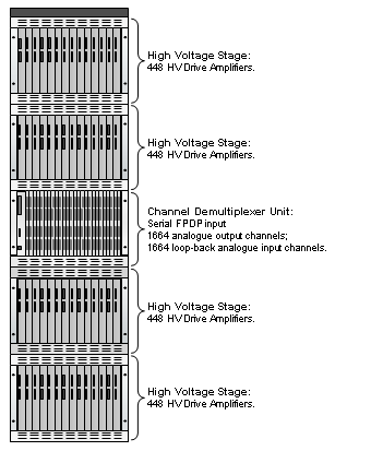
The layout on the left illustrates a 1664-channel drive with
output voltage read-back. Larger systems
are implemented with multiple CDUs,
each fed by a separate Serial FPDP link to ensure that data
bandwidth scales up with channel count.
Specification
| |
|
|
Digital Input/Output |
|
Data Interface |
Serial FPDP |
|
Data Symbol Rate |
2.5 Gbaud (1.0625 Gbaud option¹) |
|
Data Physical Connector |
Fibre-Optic Duplex LC |
|
Cable Media |
50μm or 62.5μm multi-mode fibre |
|
Maximum Fibre-Optic Cable Length |
300m |
|
Input Data Rate |
120 Msamples/sec. (16-bit samples) |
|
Output Data Rate |
120 Msamples/sec. (16-bit samples) |
|
Frame Write Rate |
70 kHz max. (1664-word frame) |
|
Control Interface |
10/100 Base-T Ethernet, RS232 |
| |
|
|
Analogue Output |
|
Output Channels per Unit |
1664 (optionally 3328 without read-back) |
|
Output DAC Resolution |
16 bits |
|
Output DAC Update Rate |
120 Msamples/sec. |
|
Output DAC Frame Rate |
70kHz max. (1664-word frame) |
|
Output Signal Range |
± 2.5V |
|
Output Analogue Signal Connector |
68-way 0.8mm pitch VHDCI |
|
Analogue Signals per Connector |
32 |
| |
|
|
Analogue Input |
|
Read-back Input Channels per Unit |
1664 (optionally 0) |
|
Input (read-back) ADC Resolution |
14 bits |
|
ADC Conversion Time |
10μs (simultaneous sampling, all channels) |
|
ADC Frame Read Time |
110μs (1664-word frame) |
|
Read-back ADC Frame Rate |
8 kHz max. (1664-word frame) |
|
Input Signal Range |
± 5V |
|
Input Analogue Signal Connector |
68-way 0.8mm pitch VHDCI |
|
Analogue Signals per Connector |
32 |
| |
|
|
Serial FPDP Interoperability |
|
Link Rates Supported |
2.5 Gbaud (1.0625 Gbaud build option¹) |
|
Serial FPDP Functions Supported |
Transmitter and Receiver |
|
Receiver Flow Control |
Always active |
|
Transmitter Flow Control |
Always active (???) |
|
Receive FIFO size |
256k 32-bit words |
|
CRC Support |
Always active |
|
Transmitter Copy Master Mode |
Not supported² |
|
Receiver Copy Mode |
Not supported² |
|
Receiver Copy/Loop Mode |
Not supported² |
|
Media Supported |
Short Wave (850nm) Laser |
|
Media Connector |
Duplex LC |
|
Fiber Transmit Data Frames Supported |
Normal Data Fiber Frames, Sync without Data Fiber Frames |
|
Transmitter stop in response to NRDY? |
Always |
|
Status updated when no data? |
Yes, empty frames transmitted |
| |
|
|
Write Latency Budget |
|
Transmitter to Receiver Latency |
<1μs |
|
Data Receive to DAC Write Latency |
<0.1μs |
|
DAC Settling Time |
<15μs |
| |
|
|
Physical Characteristics |
|
Enclosure Dimensions |
6U × 19 inch sub-rack |
|
Power Consumption |
50W |
| |
|
|
¹ The link data rate on an interface is fixed,
it is not possible to switch between 2.5 Gbaud and 1.0625 Gbaud
rates on a single device. The link rate must be specified
as a build option, and cannot be altered in operation.
² The Demultiplexer's Serial FPDP interface is aimed at
point-to-point communication
for lowest latency. It does not support daisy-chaining,
and it does not support non-standard scatter/gather
modes.
Where elaborate connection topologies are required,
a third-party Serial FPDP Switch may be used.
³ All specification data are preliminary and subject to
change without notice.
© 2005 Starpoint Adaptive Optics Limited